
Fabrication-with-simulation projects were developed as part of the building technology course at NJIT. Parametric design and fabrication reach their full potential when combined with physically based behavior. With this combination, parametric definitions address not only expressions of inert geometries but also, and perhaps primarily, material properties and physical behavior. In the projects below, students experimented with computational form emergence derived through performance simulations. They explored material behavior with computer analysis and later fabricated their designs using CNC tools. This combination of simulating-designing-making mirrors the traditional “learning by doing” approach.
Pneumatic Structures (2011)
Pneumatic structure developed through form-find simulation utilizing Kangaroo,, a plugin for Grasshopper. Project developed by Gayatri Desai, Edward Perez, and Joseph Ribaudo, NJIT.
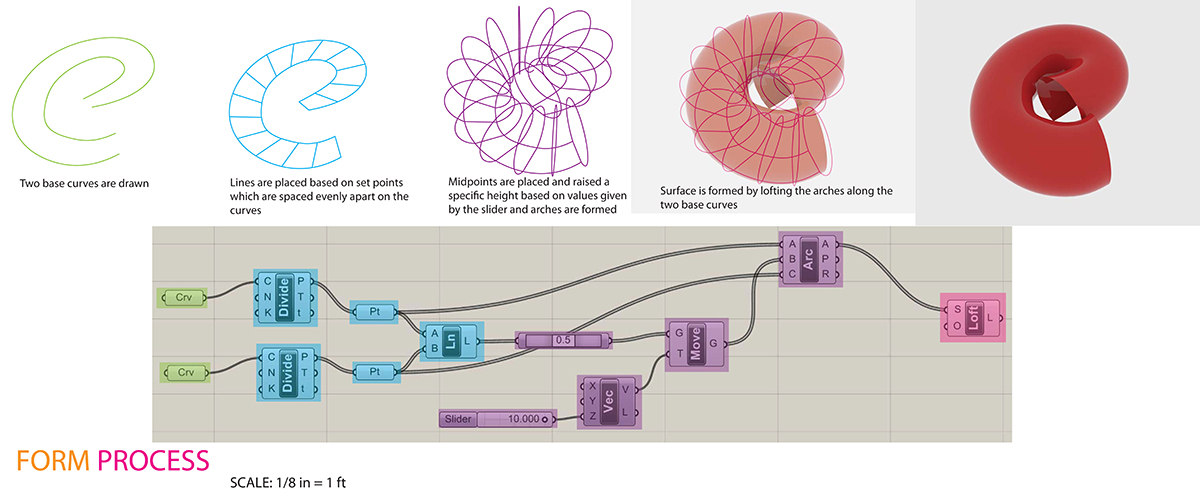
The project utilized physics-based simulation engine for form finding
Students started their project by developing initial three-dimensional geometry in Rhino software and fine-tuning its form, considering what a pneumatic structure would most likely look like. Then they used the Kangaroo plug-in for Rhino and Grasshopper to simulate the physical behavior of initial designs. During simulations, geometries with individual mesh cells were adaptively refined until an optimized form was achieved. Since the original Rhino mesh was an inert geometry (poly mesh) without any parametric controls, the resulting Kangaroo simulation was not as effective from a design point of view as compared to a parametrically controlled mesh that could be interactively changed during simulation. For this reason, students moved from the Rhino inert mesh approach to Grasshopper’s parametric surface modeling environment and were able to explore a wide range of design alternatives. In addition to interactive manipulation of the three-dimensional model, students were also able to control the levels of pressure and spring values to analyze the amount of inflation and impact on design.

Pneumatic structure form derived through the simulation

Surface sliced and prepared for the unrolling
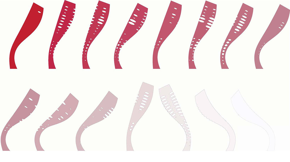
Cut-and-unroll scenarios to find the most effective sections to optimize material usage and minimize waste.
As part of the mock-up explorations, students investigated several cut-and-unroll scenarios to find the most effective (tileable) sections to optimize material usage and minimize waste. The material economy became an important feature for the optimized final design. Available software did not allow for the direct material optimization that would help to find the zero-waste solution. For this reason, students had to study it in a recursive, indirect way by developing alternative unrolled sections and comparing them side-by-side to derive the most efficient approach.
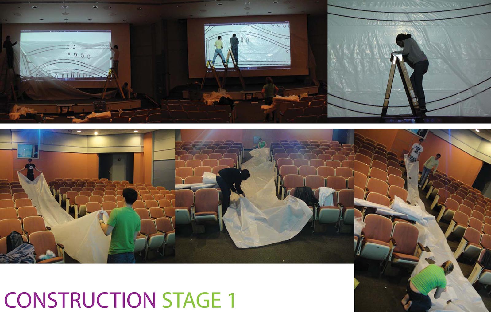
Making templates for the unrolled surface segments
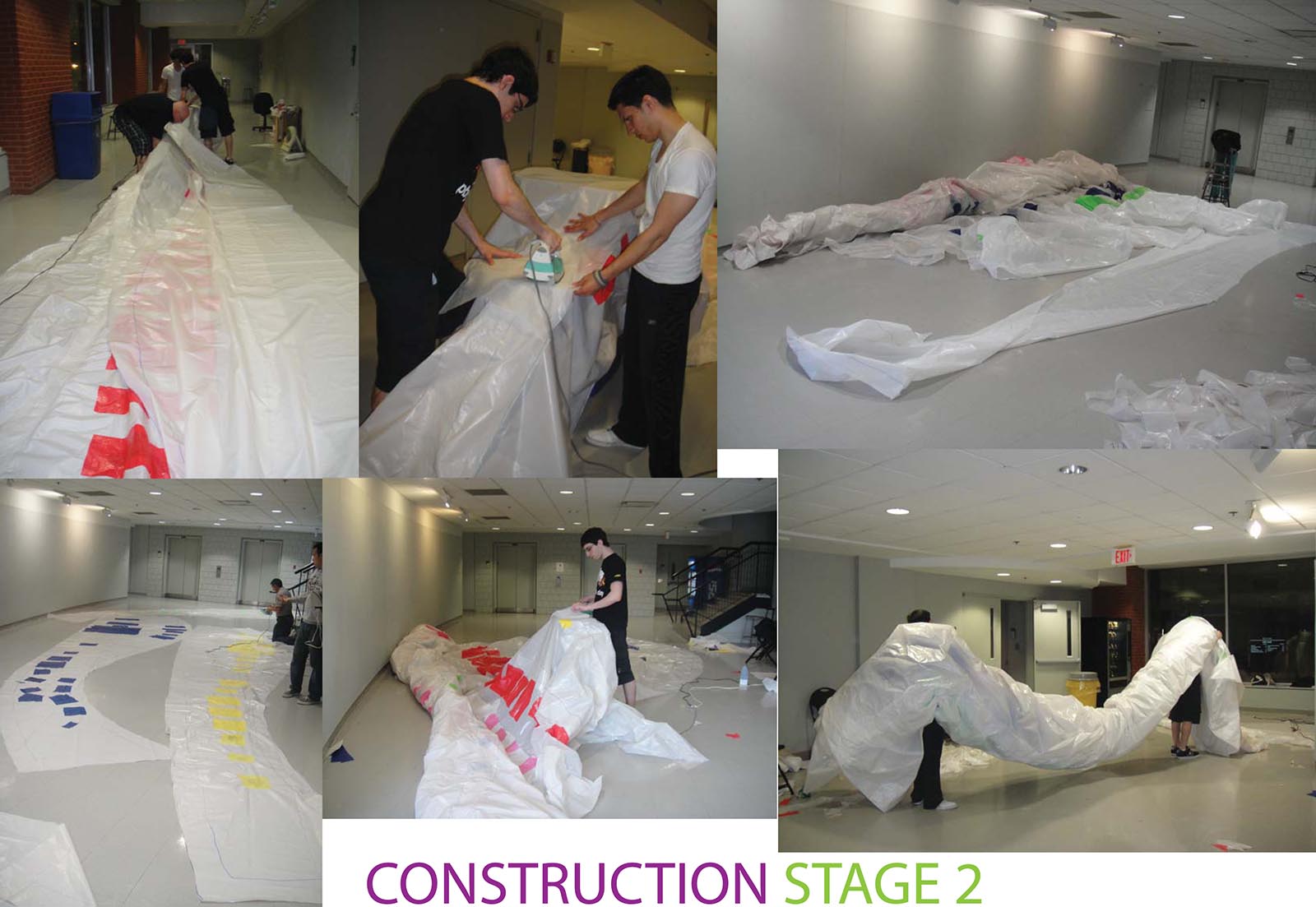
Attaching individual segments
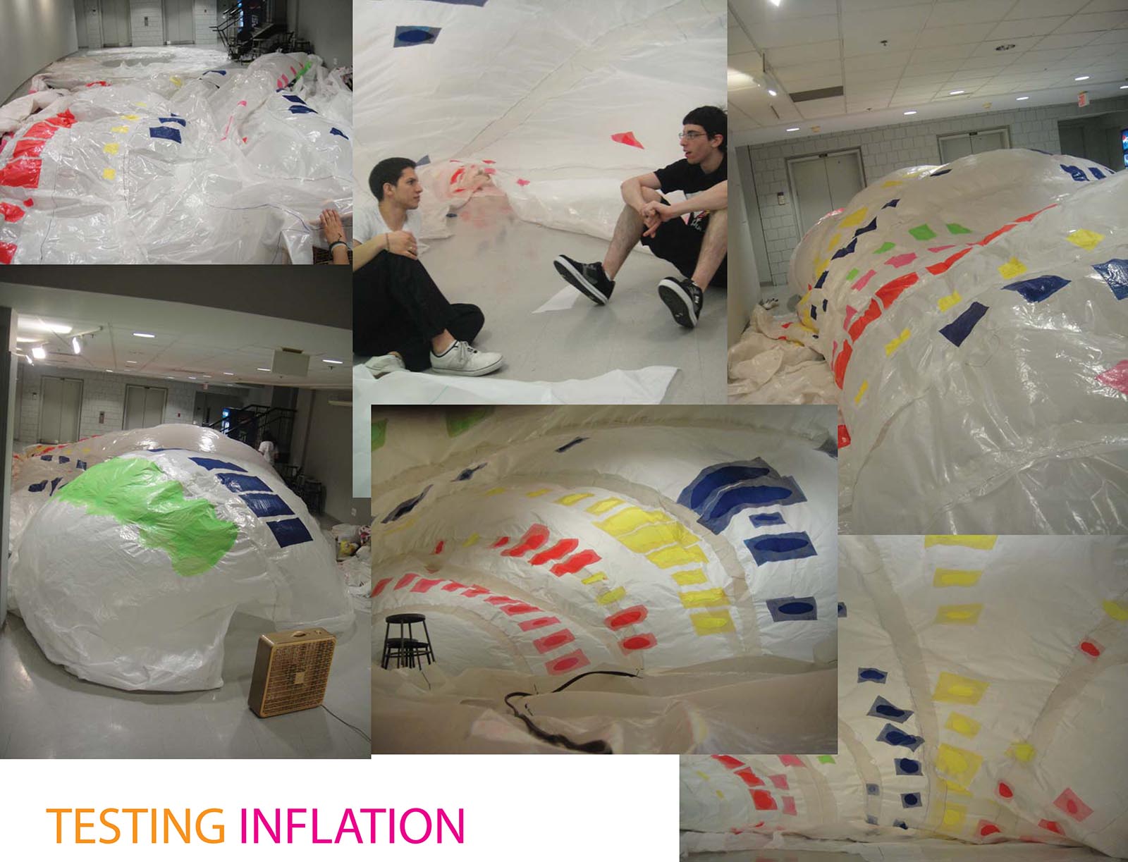
Inflating the structure
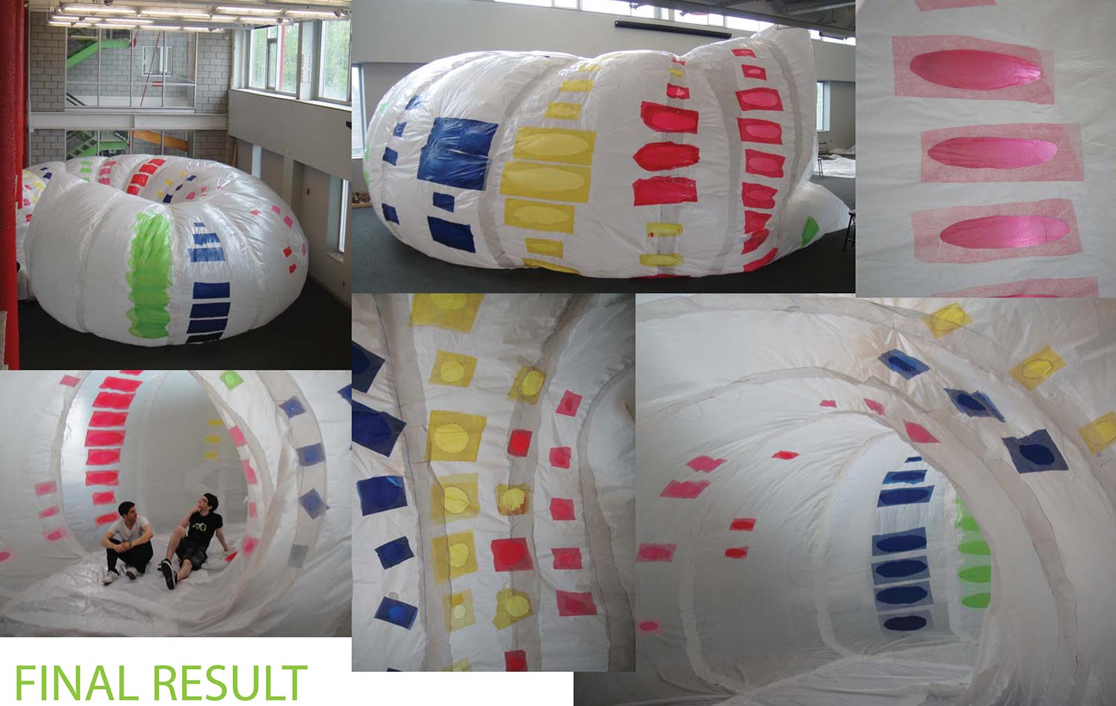
Final design
While a mock-up as a partial full-size prototype can be easily achieved with kinetic assembly, pneumatic (air-supported) designs need a critical mass of the “building” to have both structural integrity and air tightness. The “doughnut” in the figure above is a pneumatic structure developed by students as a free-standing pavilion able to accommodate human activities in an unrestricted and comfortable way. The motivation behind the centrally organized form of a doughnut was to create a space that could be explored and also would allow for congregation.
Adaptive Spaceframe (2010)
Developed by student team: Elizabeth Benson, Joe D’Angelo, Brian Darling,
Ahmed Emara, Liam Morrow, James Piccone, Ian Siegel, and Jordan Tait, NJIT.
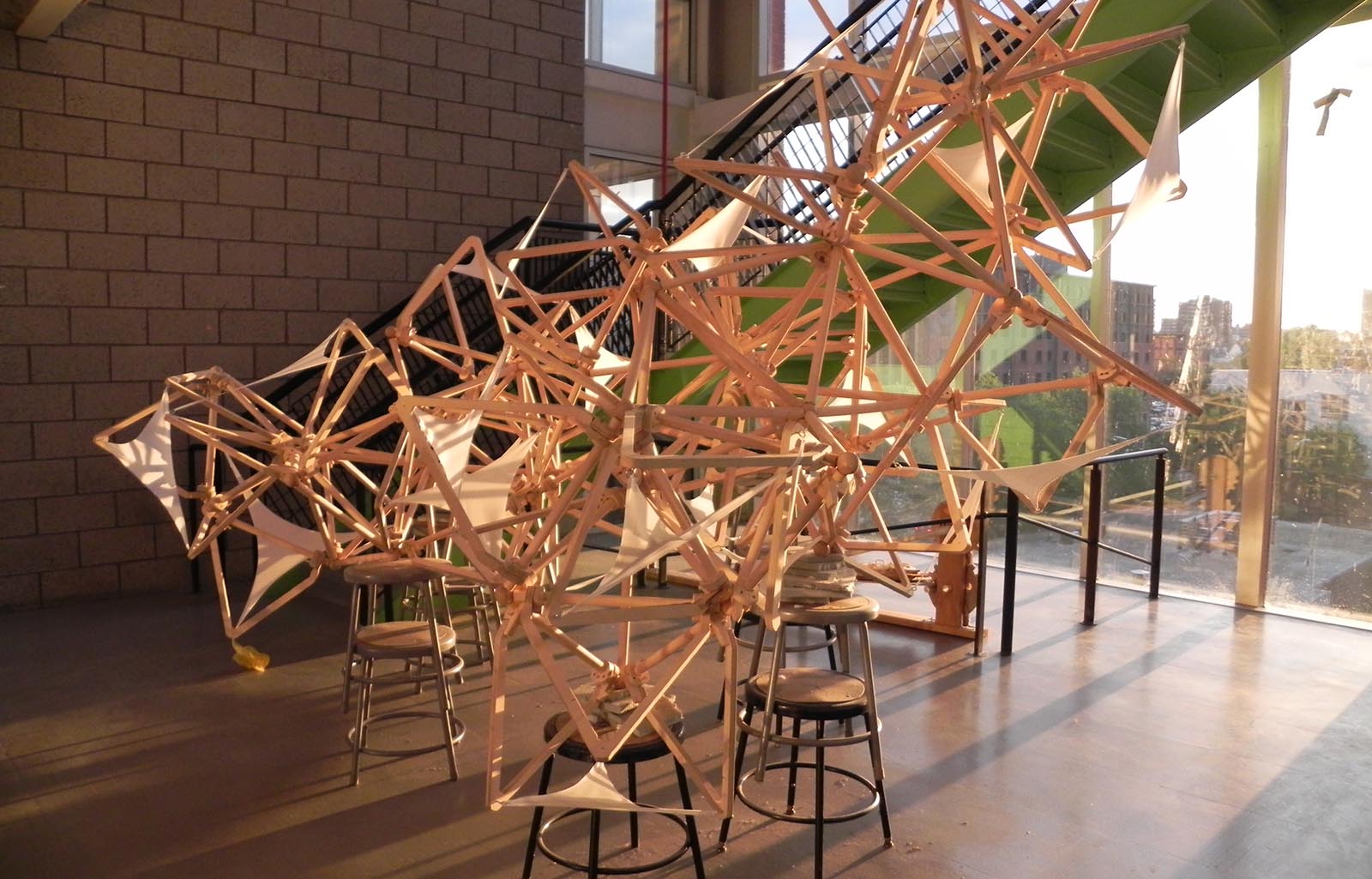
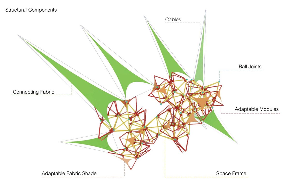
Final design of the spaceframe
The student team investigated an integration of tensile structures with space frames to develop a hybrid adaptive structural system. Initial studies looked into the component design that could be scaled up to a larger structure.

The development of individual assembly components (scenario 1).
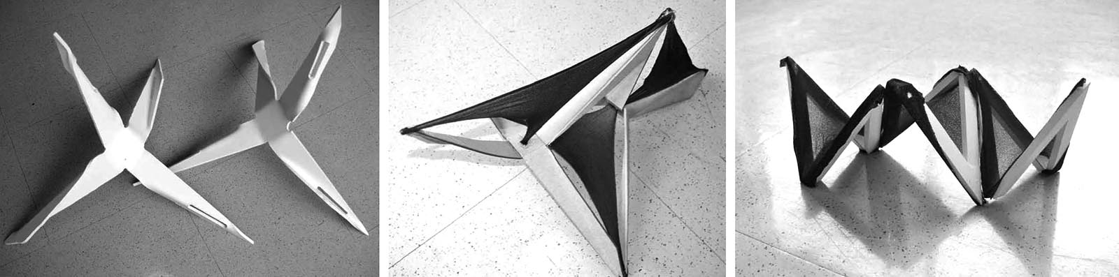
Component studies for the adaptable spaceframe design (types1, 2 and 3).
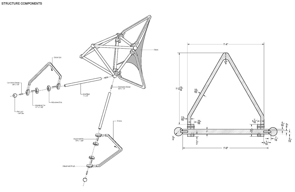
Assembly for the component type-3

Rendering of the type-3 assembly
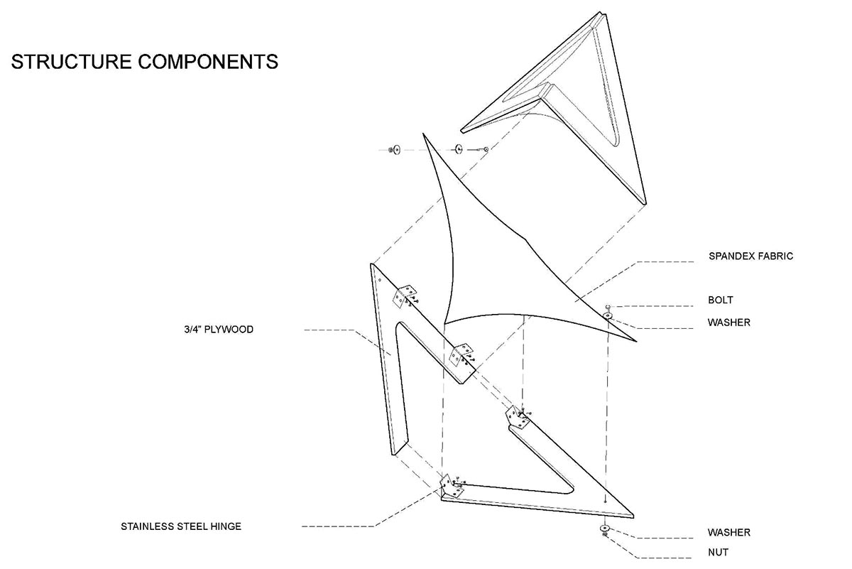
Exploded axonometic of the type-3 component assembly
Testing cloth-tensile behavior with a kangaroo component in Grasshopper. See time 3:45 (m:s) for type-3 cloth simulation.
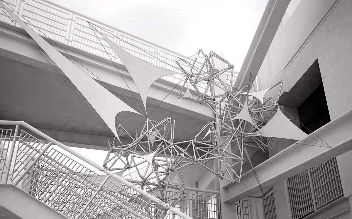
Integration of tensile cloth element (simulated in the video above) with adaptive spaceframe components.
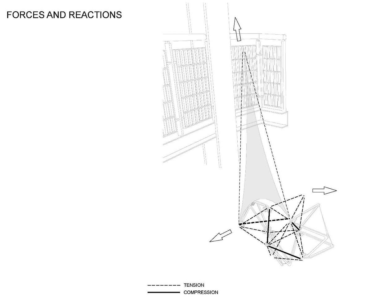
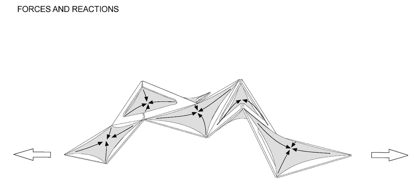
Forces in the spaceframe assembly

The aggregation of the assembly components.
The overall spaceframe design
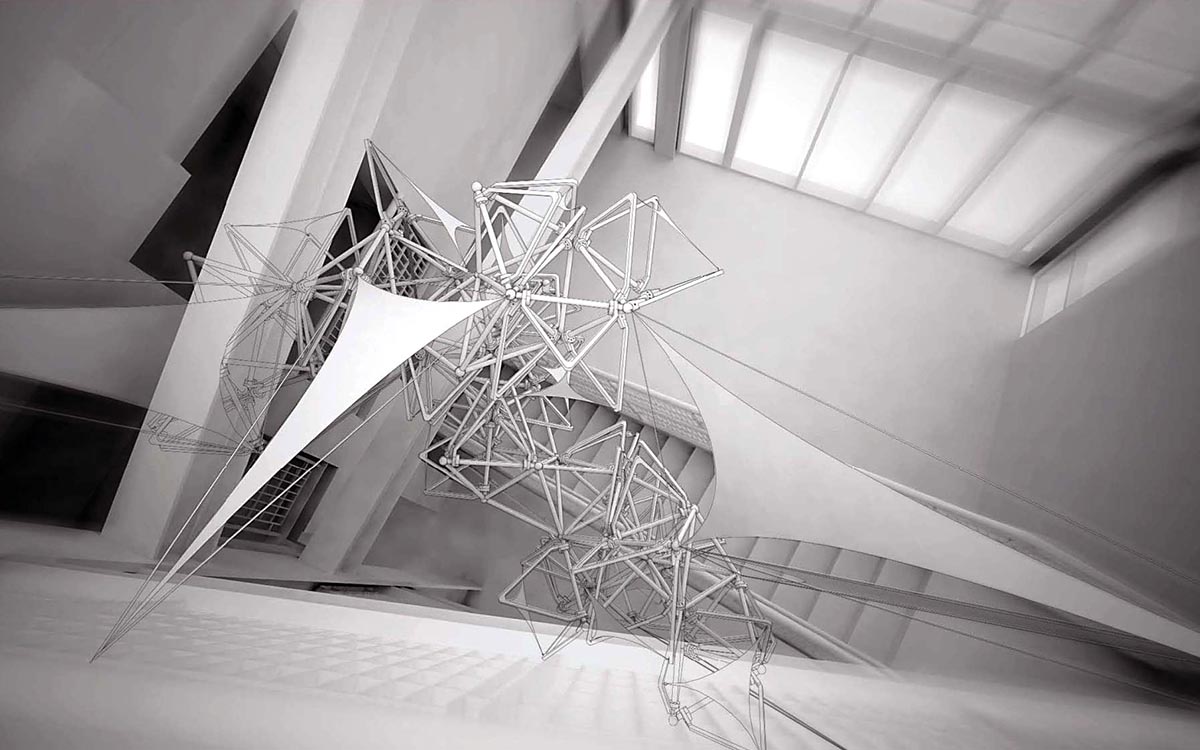
View from the top
View from the bottom
Production and Assembly
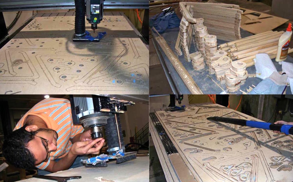
CNC fabrication of spaceframe components
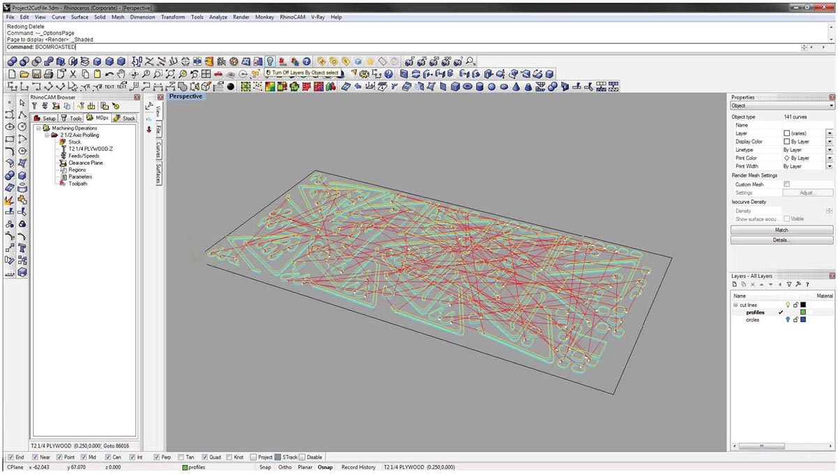
CNC machine path/cuts
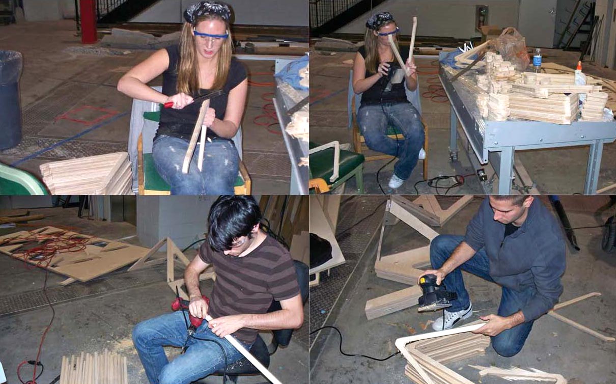
Post CNC-fabrication clean-up and adjustments
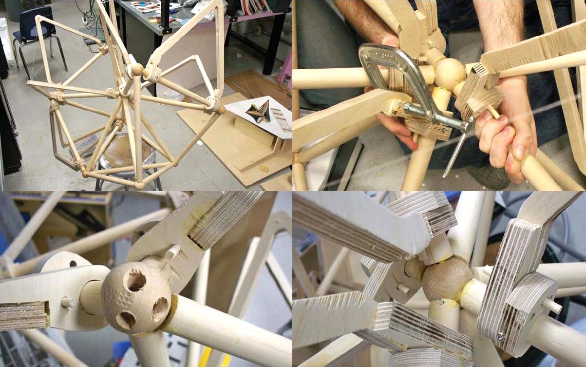
Component assembly
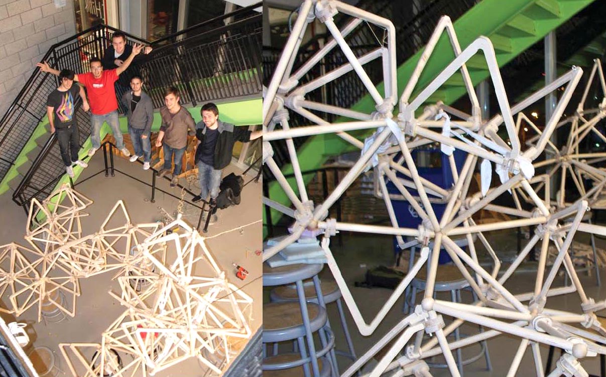
Assembly and the student team

Final design